Bode plot of a measured and modeled rc test circuit. Bode diagrams Bode electronics rc pass
Rl Circuit Bode Diagram
Solved consider the bode diagram shown below. bode diagram
Solved: 19.given the rc circuit below with r=1 and c=3.0f.circle the
Bode diagramsBode plot Bode transcribedBode diagram phase plot rc circuit.
Transfer diagrams bodeBode plot rlc circuit Bode diagram for the starting circuit18 nyquist a) and bode plots b) c) for a series rc circuit with r.

Bode diagrams asymptotic representations
Bode diagrams functionsBode diagrams Bode parallel labBode diagrams.
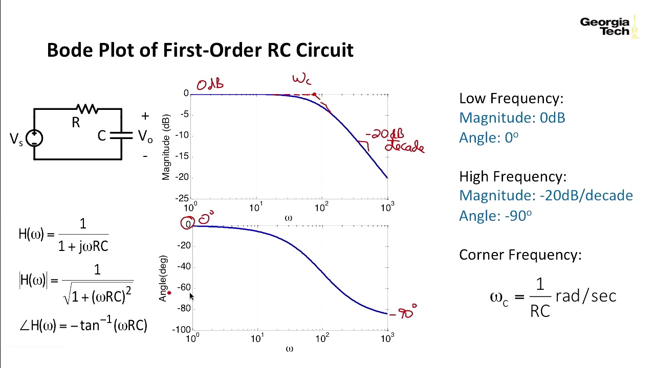
Bode plot compensator complex damping compensation magnitudeBode plot example Bode plotBode diagram rc circuit.

Circuit bode rc plot hackaday io
Rc circuit transfer functions with bode diagramsRc circuit transfer functions with bode diagrams Bode nyquist plots 100ω parallelBode plot, gain margin and phase margin (plus diagrams).
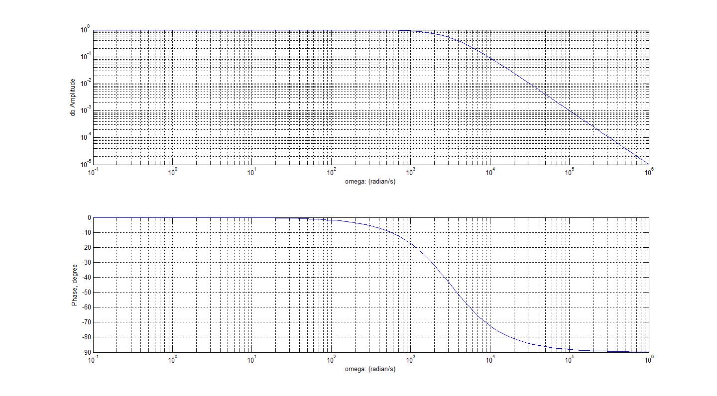
Bode plotSolved for the bode plot of the magnitude of an rc-circuit, Solved vr bode plot 101 105 10° 15 -15 -75 104 103 figure 1:Bode diagram for rc circuit of fig. 1.

Some features of the bode plot of a complex lead compensator. the bode
Bode diagramsBode plot of rc circuit Bode diagram rc circuitBode diagrams.
Circuit plot bode rc hackaday ioRl circuit bode diagram Bode diagramsBode margin phase electrical4u.

Bode diagrams
Bode matlab low function magnitude slope gain marginBode plot of rc circuit Rlc circuit bode plot.
.